Interfacing Compass Magnetic Field Sensor Module with Arduino
Compass Magnetic Field Sensor
A Compass Magnetic Field Sensor detects the Earth's magnetic field to determine directional headings. It's widely used in navigation systems, robotics, and mobile devices for accurate orientation sensing.
Working Principle of Compass Magnetic Field Sensor
The sensor works by detecting changes in the Earth's magnetic field using magnetoresistive or Hall effect technologies. It provides directional data, often as a digital signal, which the Arduino can interpret to determine the compass heading.
Experiment of Code
The compass sensor continuously monitors the Earth's magnetic field and provides real-time heading data. Arduino reads this data via I2C and processes it to determine the orientation of the device relative to magnetic north.
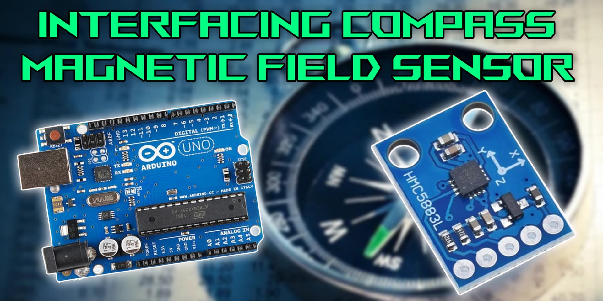
Wiring the Compass Sensor to Arduino
To wire the compass sensor, connect the VCC to 3.3V or 5V, GND to ground, and SDA/SCL to the I2C pins on the Arduino (typically A4 and A5 on an Uno). Use pull-up resistors if necessary for stable communication.
Types of Compass Magnetic Field Sensors
3-Axis Magnetometer
- Detects Earth's magnetic field on all three axes.
- Outputs raw data or processed heading values.
- Can be used with tilt compensation for more accurate readings.
Hall Effect Compass Sensor
- Detects changes in voltage caused by magnetic fields.
- Translates these changes into heading information.
- Provides high sensitivity for directional sensing.
Pin Configuration of Compass Magnetic Field Sensor
HMC5883L Sensor Module
- VCC: Connect to 3.3V or 5V on Arduino.
- GND: Connect to GND on Arduino.
- SDA: Connect to A4 on Arduino (for I2C communication).
- SCL: Connect to A5 on Arduino (for I2C communication).
Algorithm
Initialize Components
- Connect VCC, GND, SDA, and SCL pins to Arduino.
- Include necessary libraries (e.g., Wire, HMC5883L).
Write the Code
- Start I2C communication using Wire.begin().
- Initialize the sensor in setup() function.
- Read X, Y, Z axis data in loop() and calculate heading angle.
Display Values or Control Devices
- Print heading values to serial monitor.
- Use orientation data to guide robotic direction or trigger actions.
Test the Project
- Upload the code to Arduino.
- Rotate the sensor and observe heading changes in real-time.
Arduino Code
1#include <Wire.h>
2#include <Adafruit_Sensor.h>
3#include <Adafruit_HMC5883_U.h>
4
5// Create a sensor object
6Adafruit_HMC5883_Unified mag = Adafruit_HMC5883_Unified(12345);
7
8void setup() {
9  Serial.begin(9600);
10  // Start communication with the sensor
11  if (!mag.begin()) {
12    Serial.println("HMC5883L not detected. Check your wiring!");
13    while (1);
14  }
15  Serial.println("Compass Sensor Ready");
16}
17
18void loop() {
19  sensors_event_t event;
20  mag.getEvent(&event);  // Get sensor data
21
22  float heading = atan2(event.magnetic.y, event.magnetic.x);  // Calculate heading in radians
23
24  // Convert radians to degrees
25  float declinationAngle = 0.22; // Adjust based on your location
26  heading += declinationAngle;
27
28  if (heading < 0)
29    heading += 2 * PI;
30  if (heading > 2 * PI)
31    heading -= 2 * PI;
32
33  float headingDegrees = heading * 180 / PI;  // Convert to degrees
34
35  Serial.print("Heading: ");
36  Serial.print(headingDegrees);
37  Serial.println("°");
38
39  delay(1000);
40}
41
Applications
- Autonomous robot navigation
- Drone orientation systems
- GPS-based tracking devices
- Electronic compasses
- Augmented reality setups
- Portable mapping tools
Conclusion
Interfacing a compass magnetic field sensor with Arduino is a great way to add orientation and navigation capabilities to your projects. With proper wiring and code, you can easily detect direction and build intelligent systems.